Murata Launches Innovative Device for Coupling Parasitic Antenna Elements
With its compact dimensions of 1 mm x 5 mm, Murata's groundbreaking passive component marks a pioneering move for Wi-Fi 6E and Wi-Fi 7 products with space limitations.
Murata unveils a fresh addition to its product line: a parasitic element coupling device, crafted to enhance antenna performance in devices equipped with multi-band antennas, optimizing wireless connectivity.

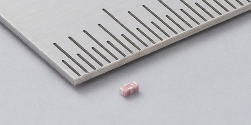
The LCPC15 is only 1 mm x 5 mm.
At just 1 mm x 5 mm, the four connection surface mount (SMD) LCPC15 series component (datasheet linked) is designed to electromagnetically couple passive elements to Wi-Fi 6E and Wi-Fi 7 devices such as smartphones, computers, and routers.
Antenna Basics in Terminal-Dependent Devices
To understand the need for Murata's new LCPC15 device, it's important to discuss the basics of antenna technology in modern wireless devices such as phones, game consoles, routers, and other products, where size is of paramount concern.
A single-wire antenna is called a monopole antenna, with the optimal antenna length being 1, ½, or ¼ the wavelength (λ/lambda). Wavelength can be calculated by taking the reciprocal of the frequency. λ = 1/f. Generally, antennae are most efficient at multiples or fractions of 2 of the signal wavelength (λ/(2n)). A dipole antenna has two monopoles extending from the point where the radiating signal attaches. Each dipole being ¼ λ will deliver optimal performance with minimal losses.

Parasitic element coupling device placement.
When space permits, parasitic elements are added parallel to the active antenna element to increase the antenna gain. Parasitic elements are not electrically connected to the amplifier or receiver. They are parallel conductors that are electrically insulated from the active antenna element and are electromagnetically coupled by being placed a specific fraction of a wavelength away from the active element.
Smartphones need to communicate over multiple frequencies and use unequal length dipole, with each side matching ¼ λ for one frequency. This is referred to as a multi-band antenna. Most cell phones have more than one multi-band antenna.
Parasitic Elements Improve Antenna Gain
Depending on the length and position relative to the active element, parasitic elements either reflect the signal or resonate with it. In either case, they increase the antenna gain. By optimizing the length, these elements can also improve multi-band transmission and reception characteristics.

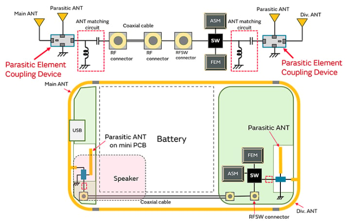
Block diagram of smartphone antenna system
The new component from Murata connects on one side between the radio and the active antenna and on the other side between the parasitic element and the ground. Electrically, the element is created with two parallel inductors—essentially making it a transformer. This electromagnetically (not electrically) couples the active side to the passive side. By tuning the geometry of the coils, the device effectively couples the two sides and increases the gain of the broadband antenna.
Wi-Fi 6E and Wi-Fi 7 Require Optimization
To give you a frame of reference, a 2.4-GHz signal has a wavelength of 4.16” (1.06 cm). A 6-GHz Wi-Fi 6E or Wi-Fi 7 signal has a wavelength of 1.667” (4.23 cm). Such short wavelengths should make antenna creation easier. However, the cell phone is a terrible environment for antenna efficiency; it is size-constrained and full of obstructions like batteries, display screens, and printed circuit boards.
The other challenge that comes with short wavelengths is that tiny changes in the length of the elements can cause big problems. Manufacturing process variations that may not have been an issue with lower frequencies (longer wavelengths) can have a great impact on antenna performance at small geometries. The LCPC15 series component is designed to optimize parasitic elements in the new, more critical Wi-Fi 6E and 7 environments.
All images used courtesy of Murata


